Emerson 3051S manuals
Owner’s manuals and user’s guides for Measuring, testing & control Emerson 3051S.
We providing 6 pdf manuals Emerson 3051S for download free by document types: Quick Start Manual, Specifications, User Manual
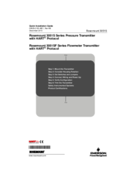
Emerson 3051S Quick Start Manual (34 pages)
Brand: Emerson | Category: Measuring, testing & control | Size: 2.49 MB |

Table of contents

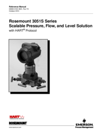
Emerson 3051S Specifications (188 pages)
Brand: Emerson | Category: Measuring, testing & control | Size: 9.84 MB |
Table of contents
5
18
29
29
29
34
52
54
65
91
92
99
103
104
110
120
122
131
133
135
138
140
143
148
148
157
159
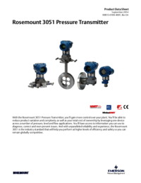
Emerson 3051S Specifications (240 pages)
Brand: Emerson | Category: Measuring, testing & control | Size: 13.48 MB |
Table of contents

Emerson 3051S Specifications (240 pages)
Brand: Emerson | Category: Measuring, testing & control | Size: 11.61 MB |
Table of contents

Emerson 3051S Specifications (222 pages)
Brand: Emerson | Category: Measuring, testing & control | Size: 9.60 MB |
Table of contents
1
5
21
27
33
34
39
81
95
95
101
103
104
104
104
111
120
123
166
169
174
185
186
187
217
218
219
220
Emerson 3051S User Manual (84 pages)
Brand: Emerson | Category: Measuring, testing & control | Size: 5.46 MB |
Table of contents
61
More products and manuals for Measuring, testing & control Emerson
| Models | Document Type |
|---|---|
| Solu Comp Xmt-P-FF/FI |
Instruction Manual
Emerson Solu Comp Xmt-P-FF/FI Instruction manual [en] ,
124 pages
|
| CSI 9420 |
User Manual
9420 Datasheet,
10 pages
|
| Solu Comp Xmt-P-FF/FI |
Instruction Manual
Emerson Solu Comp Xmt-P-FF/FI Instruction manual,
156 pages
|
| CMF200A |
User Manual
Micro Motion® 2-Wire Coriolis Flow and Density Meter with MVD,
24 pages
|
| Rosemount 644h |
Manual
Emerson Rosemount 644h Product manual,
68 pages
|
| 396P |
User Manual
Emerson 396P User's Manual,
54 pages
|
| 3051N |
User Manual
Emerson 3051N User's Manual,
100 pages
|
| 1066 Liquid Analytical Transmitter |
Instruction Sheet
Emerson 1066 Liquid Analytical Transmitter Instruction Sheet,
20 pages
|
| Rosemount 1151 Pressure Transmitter |
User Manual
Emerson Rosemount 1151 Pressure Transmitter User's Manual,
22 pages
|
| Transmitter LTM-300 |
Operations Instructions
Emerson Transmitter LTM-300 Operating Instructions [en] ,
20 pages
|
| Transmitter IP2046IM |
User Manual
Emerson Transmitter IP2046IM Instruction and Maintenance Manual,
48 pages
|
| 6081-P |
Instruction Sheet
Emerson 6081-P Instruction Sheet,
16 pages
|
| Model Solu Comp II |
User Manual
Emerson Model Solu Comp II User's Manual,
87 pages
|
| DLC3010 |
Quick Start Guide
Emerson DLC3010 Quick Start Guide,
44 pages
|
| DLC3010 |
Datasheet
Emerson DLC3010 Data Sheet,
16 pages
|
| Rosemount 2051 Wireless Pressure Transmitters |
User Manual
Emerson Rosemount 2051 Wireless Pressure Transmitters User's Manual,
154 pages
|
| 6081-P |
User Manual
Emerson 6081-P User's Manual,
62 pages
|
| Rosemount 2230 |
User Manual
Emerson Rosemount 2230 User's Manual,
80 pages
|
| DLC3010 |
Instruction Manual
Emerson DLC3010 Instruction Manual,
116 pages
|
| 5081-T |
Instruction Manual
Emerson 5081-T Instruction Manual,
98 pages
|


© 2020, manymanuals.com. All rights reserved. | 0.072 s |
 Manymanuals.com
 Manymanuals.de
 Manymanuals.fr
 Manymanuals.it
 Manymanuals.pl
 Manymanuals.cz
 Manymanuals.es
 Manymanuals-pt.com