Emerson 1F80-0471 Operations Instructions
Browse online or download Operations Instructions for Thermostats Emerson 1F80-0471. Emerson 1F80-0471 Operating instructions User Manual
- Page / 16
- Table of contents
- TROUBLESHOOTING
- BOOKMARKS
- APPLICATIONS 1
- SPECIFICATIONS 1
- INSTALLATION 2
- WIRING CONNECTIONS 2
- THERMOSTAT QUICK REFERENCE 3
- INSTALLER/CONFIGURATION MENU 4
- OPERATING YOUR THERMOSTAT 6
- IMPORTANT! 6
- TROUBLESHOOTING 8
- APLICACIONES 9
- ESPECIFICACIONES 9
- INSTALACIÓN 10
- MODO Rápido Medio Lento 13
- FA ME SL 13
- Frío (SS) 1.2°F – 1.7°F 13
- CÓMO USAR EL TERMOSTATO 14
- ¡IMPORTANTE! 14
- SOLUCIÓN DE PROBLEMAS 16
Summary of Contents
Index PageInstallation 2Wiring Connections 2Thermostat Quick Reference 3Installer Confi guration Menu 4Operating Your Thermostat 6Programming 6Troubles
La instalación del termostato y de todos los componentes del sistema de control debe ajustarse a las normas del código NEC para los circuitos Clase II
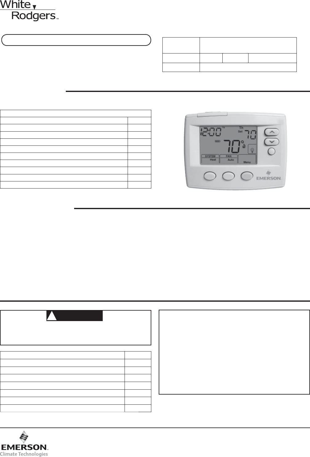
3HoraDía de la semanaTemperaturade ajusteTemperaturaambienteSubir/Bajar temperaturBotón HOLDBotón SYSTEMBotón FANIndicador SYSTEMIndicador FANBotón ME
4MENÚ INSTALADOR/DE CONFIGURACIÓNCon el termostato en Heat, Cool o Auto, en operación normal, presione el botón Menu durante 5 segundos como mínimo. L
5MENÚ INSTALADOR/DE CONFIGURACIÓN Cuando esta función está en OFF (desactivada), no se realizarán cambios cuando el sistema de enfriamiento está func
6CÓMO USAR EL TERMOSTATOElija la confi guración del ventilador (Auto/On)Coloque el interruptor FAN en Auto (automático) u On (activado).Auto es la confi
7Pre-programación de ahorro de energía de fábricaLos termostatos 1F80-0471 están programados con los ajustes de ahorro de energía indicados en la sigu
Síntoma Causa posible Acción correctivaEl sistema no cali-enta/El sistema no enfría/No funciona el ventilador (problemas comunes)1. Se quemó el fusibl
Thermostat installation and all components of the control system shall conform to Class II circuits per the NEC code.WARNING!INSTALLATIONRemove Old Th
3TimeDay of WeekSettingTemperatureRoomTemperatureTemperature Up/DownHOLD ButtonSYSTEMButtonFANButtonSYSTEMIndicatorFANIndicatorMENU/SCHEDULE/RUNButton
4INSTALLER/CONFIGURATION MENU With thermostat in Heat, Cool or Auto, in normal operation, press the Menu button for at least 5 seconds. The display wi
5INSTALLER/CONFIGURATION MENU4) Energy Management Recovery: (this step is skipped if confi gured to be non-programmable). Energy Management Recovery
6OPERATING YOUR THERMOSTATChoose the Fan Setting (Auto or On)Set the FAN Switch to Auto or On.Fan Auto is the most commonly selected setting and runs
7Energy Saving Factory Pre-ProgramThe 1F80-0471 thermostats are programmed with the energy saving settings shown in the table below for all days of th
Symptom Possible Cause Corrective ActionNo Heat/No Cool/No Fan(common problems)1. Blown fuse or tripped circuit breaker.2. Furnace power switch to OFF
Instalación 2Conexiones eléctricas 2Guía de referencia rápida del termostato 3Menú instalador/de confi guración 4Cómo usar el termostato 6Programac
Related products and manuals for Thermostats Emerson 1F80-0471
 (20 pages)
(32 pages)
(18 pages)
(20 pages)
(32 pages)
(18 pages)
© 2020, manymanuals.com. All rights reserved. | 0.041 s |
 Manymanuals.com
 Manymanuals.de
 Manymanuals.fr
 Manymanuals.it
 Manymanuals.pl
 Manymanuals.cz
 Manymanuals.es
 Manymanuals-pt.com
Comments to this Manuals